Connections can be created using the mouse control.
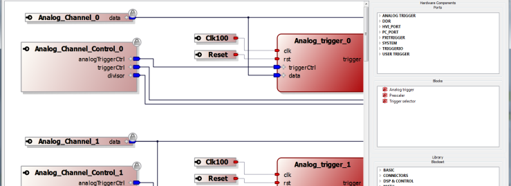
In the image below, connections are made by clicking on an output port and then dragging the line from it to a suitable input.
Connections can be created according to connection rules, which are explained in Connecting Ports
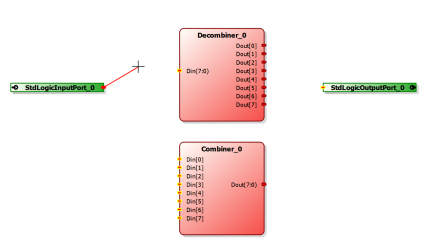
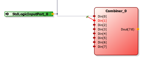
If a connection can be made from a connector, a new line appears from this connector to mouse and the mouse cursor changes to the axis icon as shown below. Furthermore, the possible target connectors are highlighted in yellow color for showing the different connection possibilities. See the input ports on the lower block "Combiner_0" shown below.
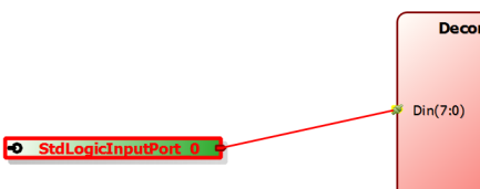
For finishing the connection, the end of the connection line is dragged by the mouse to a compatible target connector. In this case, the mouse icon changes to green connection icon can be seen.
When the mouse button is released, the new connection is created.
Otherwise, attempting to create a connection from a connector which does not accept new connections, the forbidden icon as mouse cursor appears as follows.
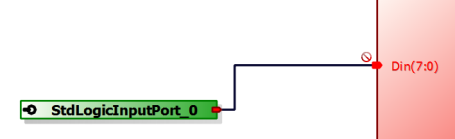
When making multiple connections, it is not needed to connect directly for example from a common source to multiple input ports. The ports can be connected together at the target. For example, in the following image, Din[0] is connected to StdLogicInputPort_0. if it is wanted to have both Din[0] and Din[1] connected to StdLogicInputPort_0, Din[1] can be joined to Din[0] locally by selecting the Din[1] port with the mouse and dragging its connection line to the existing line already connected to Din[0]. Notice the green acceptable connection icon below. Once the left-hand button of the mouse is released, the connection is made locally between Din[0] and Din[1].
For example, select the mem_M and mem_S ports and drag them individually into the FPGA Block project. Connect the output of the master denoted with an "M" to the input of the slave, denoted with an "S."
Right-click the line connecting the two ports to see two options: Remove and Redraw. Remove will delete the connecting line.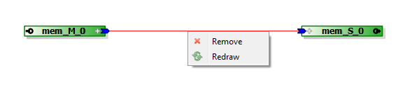
By way of an example, add a block between the two ports. Notice the line connecting the ports is now no longer straight. 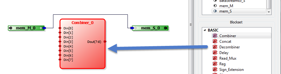
Delete the block that was just added and notice that the connecting line stays unchanged. Right-click the line and select Redraw. The line will become straight again. 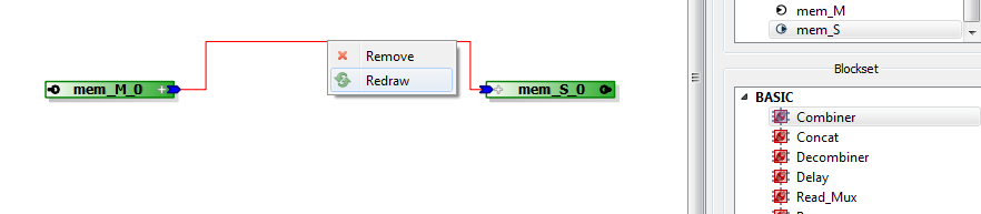
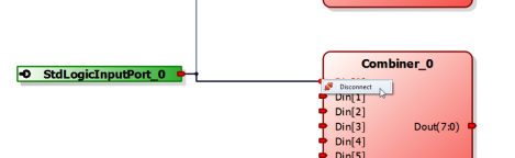
Once a connection is created, the connection can be disconnected by right-clicking with the mouse button on the connector, which brings up the Disconnect option.